HerrFarber
Active member
I'm looking to add a few things and a roadmap would be helpful.
Follow along with the video below to see how to install our site as a web app on your home screen.
Note: This feature may not be available in some browsers.
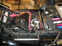
I tried using the License plate light as a trigger for my Skene tail/turn and it through a bulb fault, so be warned. If possible you should test it first before permanent install if possible.I'm thinking of using the license plate LED wire as the switched hot. I'll be all over it today. So far I've disassembled the license plate mount and it's LED. It was surprising to find it to be such a complicated design, using way more plastic parts than should be needed to do such a simple job.
PDM 60 is the solution.I tried using the License plate light as a trigger for my Skene tail/turn and it through a bulb fault, so be warned. If possible you should test it first before permanent install if possible.

With the PDM 60 you pick up only a "signal voltage" from the appropriate CANBUS circuit. The PDM unit then supplies the power to the accessory, what ever that may be. the Canbus does not "see" the power drawn by the accessory itself. You have the input trigger signal and the putput port is adjustable to the power demand of the accessory.You may need to pick up the brake signal from the front/rear brake switches rather than from the light circuitry in order to feed your addition brake light

 www.revzilla.com
 www.revzilla.com
That's exactly what I did for a running light supply.I'm thinking of using the license plate LED wire as the switched hot. I'll be all over it today. So far I've disassembled the license plate mount and it's LED. It was surprising to find it to be such a complicated design, using way more plastic parts than should be needed to do such a simple job.
I came up with the same results today. Thanks for posting it theMucker!The R18 rear lights go to a 6-pin connector under the LH side cover. And right off the bat, the color codes are not the same on both side of the male/female connector. The wires coming from the back of the bike lead to the male connector, so the female connector leads to the bike's main system. Each contact is numbered 1 thru 6 at the outboard ends of the connector bodies.
FEMALE to MALE
1- brown to brown GROUND SPLITS into 3 wires for license & each signal/brake
2- blue/green to blue/green RH Signal/Brake 12+ with signal OR brake use
3- blue/red to black/white LH Signal/Brake 12+ with signal OR brake use
4- blue/brown to blue/brown Lic. Plate Lamp SWITCHED 12+ switched 12+ (ignition ON)
5- gray/red to gray/red SPLITS into 2 wires, to each signal/brake TESTS SHOW NO IMPEDANCE CHANGE OR VOLTAGE with/without ignition or brake use, but slight impedance variation with turn signal use
6- gray/yellow to yellow SPLITS into 2 wires, to each signal/brake TESTS SHOW NO IMPEDANCE CHANGE OR VOLTAGE with/without ignition or brake use, but slight impedance variation with turn signal use
The web page changes the layout of the above test, so I've attached a .jpg to show it as I typed it.
View attachment 810
UPDATED @ 1720
Can anyone tell me where to find the acc/key ignition wire? I need to tap into it