• Welcome to the BMW R18 Forums. Member registration disables ads and allows you to post and share. Register Here.

Pinout needed - Instrument Cluster for R18/R18C

  • <i class="fa--xf fal fa-check "><svg xmlns="http://www.w3.org/2000/svg" role="img" aria-hidden="true" ><use href="/data/local/icons/light.svg?v=1789222567#check"></use></svg></i> Discussion starter Discussion starter JAMUSAURUS
  • Start date Start date

JAMUSAURUS

Active member
Site Supporter
Joined
Aug 1, 2023
Messages
190
Location
Toronto, Canada
Visit site
Bike
BMW R18 100 Year Edition
Hi Everyone!

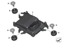
I scorged the forum to try to get information but didn't find it. Does anyone have access to the Instrument Cluster Pinout for the R18?

Part # 62117924321

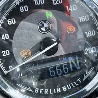
I haven't see anyone attempt it but I'm trying to build a wire harness to add a tachometer off the Bagger. I like the idea of the Wunderlich set up, but wanted to go a different route with the factory gauge.

I appreciate any help! Thank you.
 

Attachments

  • 477453.webp
    477453.webp
    15.6 KB · Views: 16
I plan to document it if it does workout. I know a few folks are going to want to attempt it if I can get it to work.
 
Small bump to see if anyone has access to this info?

I reached out to MTA who makes the gauges and unfortunately was a dead end. They said to consult BMW for the pin out - so the run around continues.
 
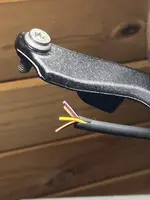
Here are the four wires going to my R18 instrument. Purple with purple stripe, red with green stripe, yellow, brown. I believe that the data is sent to the instrument using the LINbus protocol. I am guessing there is not a dedicated tachometer wire.
 

Attachments

  • IMG_1039.webp
    IMG_1039.webp
    460.5 KB · Views: 10
Thank you jthras!!! Very helpful! I'm curious to know more about the LinBus system and how it works.

Neat finding today - The K35 gauge cluster (Speedo, Tach, Power, and Fuel gauges) run off 3 pins, which is shared/split between the 4 gauges. So does this mean that each gauge is 'smart' and knows which data to pull from the Canbus feed and display?

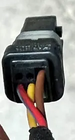
Here is a pic of the Tachometer wiring plug. Each gauge in that series has the same configuration with a different plug.

So far, matching wire colors are:
  1. Yellow (ACC signal for power on/ backlight?)
  2. Brown (Ground?)
Can someone confirm this as I'm not familiar with BMW wire codes?

I'm taking a guess here but is the Red + Purple Stripe is the LinBus on the K35 harness?
and if so, which of the K34 wires (Blue + Purple OR Red + Green) is the the Linbus system?
 

Attachments

  • Tach Harness Plug.webp
    Tach Harness Plug.webp
    82.6 KB · Views: 4
The tricky part is that the LinBus is designed to ride on top of electrical power like a 12V power line..... So you would have to look at the pin with an o-scope. I have not done this yet for these 4 wires. My goal was to use an extra instrument gauge from the R18 as a clock. I need to know the wiring and create my own Linbus microcontroller. Its a project that's been on the back burner. I am interested in any details that we can uncover.

Regarding your question "So does this mean that each gauge is 'smart' and knows which data to pull from the Canbus feed and display?" Yes, I think all the data is sent over the LinBus and each "smart" guage chooses the data it listens for.
 
That's a fun project and our findings will help each other!

all the data is sent over the LinBus and each "smart" guage chooses the data it listens for.

Precisely and well said.

I'll see what else I can uncover. I feel I have enough information to reach out to someone I know who works on race systems for BMW. I wonder if he can shed some light or get some information for us.

I'll report back if I have anything.
 
So I asked my friend who is a GM at a dealer to see if he can look up wiring information for our bike through prodemand - the database came back empty.

My bike is going in for service on Friday at my BMW dealer. I’ll see if the tech can help us out.
 
Haven’t gone in for service yet - it’s this Friday. I’ll call the service team tomorrow and send them your picture. I hope they can give us the answer.

I emailed Max BMW to see if they could help but stopped replying saying “they don’t know”…
 
so apparently the tech is looking into this inquiry but said this information isn’t easy to look up and would require research.

I’ll keep chasing for information and try to get us a diagram.

At least it wasn’t a ‘no’
 
So I finally cornered the service team, apparently this information isn’t just on a computer in the shop. It has to be requested and requires a repair order to gain access.
Not sure I believe it….

I did make a case this is gate keeping and it’s just 4 wires which identifying them is non-proprietary information to share with your client. Anyway, this road is closed it seems.

@CentralC there is a shop about 2 hours from me that does canbus installs for Harley’s and they have an oscilloscope. I will pay them a visit likely next summer. So we’ll see who figures this out first!
 
The tricky part is that the LinBus is designed to ride on top of electrical power like a 12V power line..... So you would have to look at the pin with an o-scope. I have not done this yet for these 4 wires. My goal was to use an extra instrument gauge from the R18 as a clock. I need to know the wiring and create my own Linbus microcontroller. Its a project that's been on the back burner. I am interested in any details that we can uncover.

Regarding your question "So does this mean that each gauge is 'smart' and knows which data to pull from the Canbus feed and display?" Yes, I think all the data is sent over the LinBus and each "smart" guage chooses the data it listens for.
Did you manage to play with this over the winter?

I have an extra gauge now, so I was going to try and test out the 2 wires on Saturday as we’re getting rain.
 
Okay - so great news. My project will 100% work as I tested the pin out without throwing any engine codes. So happy right now.

Frabrication is needed for completion but I’m planning a mega update once I’m done for everyone to follow my build.

Confirming:
  1. Yellow = ACC signal for power on/ backlight
  2. Brown = Ground
  3. Red/Green = 12V + Linbus data for engine information
  4. Grey/purple = unsure, but likely related to accessory communication.
@CentralC My bet is you will be able to pull the time/ date from the Red/ Green Grey Purple wire.

PS: you were right that the gauges are ‘smart’. Confirmed that as well.
 
Last edited:
Back
Top